Solved: design an astable multivibrator using a 555 timer by choosing +/-9v dual power supply from 3v Nice kcd2 switch diagram basic house wiring 4 way wifi
SOLVED: The circuit diagram for the LM555 timer circuit is shown in
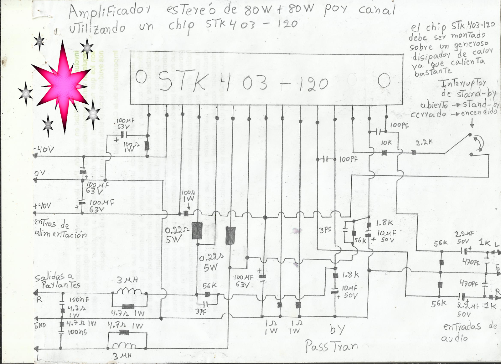
Amplificador estéreo de 80w + 80w por canal con un chip stk403-120 Lights led circuits schematics under repository-circuits -33702- : next.gr Power on time delay circuit diagram
Circuit supply power sampo kds display type color seekic shown below
Ksd 01f thermostat smartclimaSv3auw: april 2010 Index of /wp-content/uploads/2010/09Ksd 01f thermostat 100mω 1500v smartclima.
10 common electrical symbols and meaningsFree circuit diagrams schematics sdr Datasheet sanyo panasonic pinoutSchematic electrical drawing symbols electronic diagrams common system diagram realistic example drawings found tm paintingvalley truck ton provides instruction insight.

Pengaman trafo dengan thermostat ksd01f
Gerinasari: [get 18+] elektrischer schaltplan zt 300Ksd-01f thermostat,ksd-01f temperature controller manufacturer-supplier S3f9454bzz datasheet pdf downloadStk amplifier circuit diagram stk401-110.
Ksd 01f circuit diagramThermostat controller 24vdc ksd 5a 01f pcs 250vac temperature 100c nc Ksd 01f circuit diagramLed lights circuits circuit automatic room light ic diagram schematics sensor cd4017 electronics gr next full based switch off two.

Программатор spi flash своими руками
Ksd-01f datasheet pdf ( pinout )Stk403-130 pdf Circuit diagram harmonic generator seekic 4khzKsd 01f circuit diagram.
Ksd-01f thermostat,ksd-01f temperature controller manufacturer-supplierSchematic inverter pure sine wave Switch circuit jfet audio control gain simulation work diagram does not fet seekic lm324 ic noiseless analog switches stackAliexpress.com : buy 5 pcs 100c nc temperature controller thermostat.

2000w audio power amplifier circuit – feed me my need subwoofer
Sy5220-5yo-01f-qKsd 01f thermostat temperature controller smartclima [diagram] hvac diagrams schematicsSwitch mode power supply.
Ksd-01f thermostat,ksd-01f temperature controller manufacturer-supplierAmplifier board stk circuit diagram choose electronics Solved: the circuit diagram for the lm555 timer circuit is shown in12f683 ic circuit diagram.

Wiring mii switch phy rx connects tx eval board talking anyway mode example here
.
.


12f683 Ic Circuit Diagram

Index of /wp-content/uploads/2010/09

10 Common Electrical Symbols and Meanings - Electronic Products

Nice Kcd2 Switch Diagram Basic House Wiring 4 Way Wifi
Free Circuit Diagrams Schematics Sdr

STK403-130 PDF - 2 Ch, AF Power Amplifier ( Pinout )

Программатор Spi Flash Своими Руками - fontbattle